|
Project 3: Cyber Physcial System (CPS)Research
PROBLEM- we have 2 cameras (one for RGB, one for depth) and they do not see the same part of the world and yet, for our computer vision algorithms we want to know the RGB value for a pixel in our Depth image.
SOLUTION - perform calibration to get both the RGB and Depth Camera's parameters
- This is a process where we recover the absolute or relative camera (rgb and depth) parameters.
- Relative parameters lets you map:
- RGB -> U,V,Depth
- U,V,Depth -> RGB
- Absolute parameters lets you:
- RGB->U,V,Depth
- U,V,Depth ->RGB
- U,V,Depth ->X,Y,Z (real world coordinates)
|
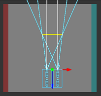
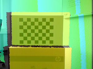
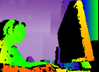
| BEFORE Calibration --- overlay of RGB and Depth (pseudo colored) |
 |
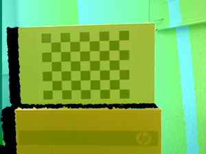
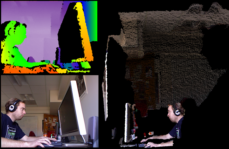
| AFTER Calibration |
 |
|
RGB image: for every pixel i,j we have the value {red, green, blue}
|
Raw Depth image: for every pixel i,j we have value {depth} = this is measurement of distance from "center" of the depth camera
|
How do we get this Calibrated Data --- there are some different possibilities
-
EASY 1 : Use methods provided by OpenNI framework
OpenNI comes with a predefined calibration stored in the firmware that can directly output aligned depth and color images with a virtual constant focal length. Most applications will be happy with this calibration and do not require any additional step. However, some computer vision applications such as robotics might need a more accurate calibration.
NOTE: OpenNI knows to look in the Kinect Firmware directory for a calibration file called data/kinect_calibration.yml that contains the calibration cameras parameters for a "generic" Kinect. --remember they try to manufacture them so the 2 cameras are located and aligned a specific way within some smaller manufacturing tolerances.
EASY 2: Use methods provided by Windows Kinect SDK
Similar to OpenNI will use the calibration cameras parameters that come with the Kinect sensor firmware.
EASY 3: Use methods provided by 3rd party NON SDK that did Calibration on THEIR Sensor (not yours)
HARDEST: Create your own calibration code and have your own calibration widgets (targets) to find points to get the camera parameters from
Note: there is a toolkit called RGBDemo that comes with two utilities to refine the predefined calibration. RGBDemo is an opensource "toolkit" that has a set of created demos for you ---you don't need to program including a Calibration program that will create a YAML file (openni_calibration.yml ) file of calibration camera parameters that can be used by OpenNI (RGBDemo program that does this is called calibrate-openni-intrinsics) --so this is only for OpenNI developers
Note: YAML human-readable data serialization format that has similar structure to XML
Why would you ever create your own calibration code? (HARDEST)
You will get BETTER accuracy than that povided by the SDKs ---as it is tuned very specifically for YOUR sensor . You may need this accuracy for an application like robotics (robot go pick up the pencil where the Kinect sensor sees it).
Are you going to go the HARDEST route --- NO!
You are going to choose one of the EASY 1, 2 or 3 methods...... I think the accuracy is going to (hopefully) be good enough for our application (afterall we are not asking the robot to go to some XYZ location and look at the person's eyelid for example).
EASY 1: Explanation of some functions-- -JUST COPY AND USE THE CODE |
Functions that tell the Kinect sensor to capture Depth and Image information and to setup so
they are ALLIGNED ---> this means the maping from raw depth pixel is the same pixel in the RGB image!!!!!!!!!!!
I am not showing you the setup code in OpenNI to setup the Kinect sensor!!!!
xn::DepthGenerator depthGen = xn:DepthGenerator(); //note that xn is the namespace in OpenNI of this class
xn::ImageGenerator imageGen = xn:ImageGenerator();
depthGen.GetAlternativeViewPointCap().SetViewPoint(imageGen); // tell OpenNI to allign the RGB and Depth
// The last line means the RGB[i][j] corresponds to the RawDepthImage[i][j] location!!!!
//getting RGB values for a depth image point is really easy
//get the Depth Image
const XnDepthPixel* pDepthMap = depthGen.GetDepthMap();
//get the RGB Image
const XnRGB24Pixel* pDepthMap = depthGen.GetRGB24ImageMap();
Function to convert an array of x,y,Raw Depth points to an array of the World X,Y,Z locations -------- this is mapping of Raw Depth (x,y,raw_depth) to World X,Y,Z
NOTE: XN_VGA_X_RES and XN_VGA_Y_RES are the dimensions of the Depth image is the x and y directions respectively.
XnUInt32 nCount = XN_VGA_X*XN_VGA_Y; //number of pixels in image
XnPoint3D rawDepth[nCount]; // need to use array of XnPoint3D instances to store the x,y,Raw depth info
//shove our Raw depth data into our new array of XnPoint3D instances
for (int x=0; x<XN_VGA_Y_RES; x++){
for(int y=0; y<XN_VGA_X_RES; y++){
rawDepthPoints[y * XN_VGA_X_RES + x ].X =
x;
rawDepthPoints[y * XN_VGA_X_RES + x ].Y =
y;
rawDepthPoints[y * XN_VGA_X_RES + x ].Z = (short) pDepthMap[y *
XN_VGA_X_RES + x];
}
}
//now convert it!!
XnPoint3D realWorldPoints[nCount]; //where we will save World X,Y,Z points
depthGen.ConvertProjectiveToRealWorld(
nCount, rawDepthPoints, realWorldPoints);
//write World Points X,Y,Z to a file
for(int count = 0; count < = nCount; ++count) {
fprintf(file,"%f %f %f\n",realWorldPoints[count].X, realWorldPoints[count].Y, realWorldPoints[count].Z);
}
fclose(file);
Function to convert an array of World X,Y,Z points (aRealWorld) to an array of the corresponding locations in raw Depth or RGB image (aProjective) -------- this is mapping of World X,Y,Z to Raw Depth location (which is same as R,G,B pixel location)
depthGenerator.ConvertRealWorldToProjective (nCount, RealWorldPoints[], ProjectivePoints[] );
// note that ProjectivePoints are the in the domain of the rawDepthPoints above.
// note it is faster to call this function for all the points you want to transform at once rather than calling one a point at a time..
//
.hence it takes an array of points as input....NOTE: if you need to do one point at a time look here for another way
// that may be faster. Basically will call OpenNI to get run time camera calibration parameter of Field of viewusing
// depthGen.getfieldOfView and then using transformation equations of
//where Xres = number of pixels in X direction in Raw Depth image
// Yres = number of pixels in Ydirection in Raw Depth image
// given we are at pixel U,V in the rawDepth image
XnFieldOfView FOV;
FovH = depthGen.GetFieldOfView(FOV);
XtoZ=tan(FOV.fHFOV/2)*2; //FOV.fHFOV = horizontal field of view
YtoZ=tan(FOV.fVFOV/2)*2; // FOV.fVFOV = vertical field of view
World.x _rw=(U/Xres-.5)*Z*XtoZ
World.y = (0.5-V/Yres)*Z*YtoZ,
World.z = rawDepth[U][V];
|
|
- you read up on the Microsoft Kinect SDK developer site.
- Again like OpenNI it uses the factory calibration parameters
- SEE Methods For Mapping.
- C++: NuiImageGetColorPixelCoordinatesFromDepthPixel
- C#: Camera.GetColorPixelCoordinatesFromDepthPixel
HRESULT NuiImageGetColorPixelCoordinatesFromDepthPixel(
           NUI_IMAGE_RESOLUTION eColorResolution,
           const NUI_IMAGE_VIEW_AREA *pcViewArea,
           LONG lDepthX,
           LONG lDepthY,
           USHORT usDepthValue,
           LONG *plColorX,
           LONG *plColorY  )
- ALSO they have Middleware for skeleton tracing that has Mapping features from its XYZ joint (of skeleton --i.e. hand,etc) to the raw depth image (X,Y,Z) and to the RGB image coordinates
- C++: NuiTransformSkeletonToDepthImage
- C# SkeletonEngine.SkeletonToDepthImage
- NOTE: to know when the frames (individual images in video sequence) are coordinated between the 3 streams the Microsoft SDK
provides (Depth, RGB and Skeleton) then use a trigger in your code called AllFramesReady event.
-
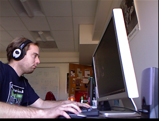
As described here and in the original Nicolos Burros calibration results the following algorithm (written in C++ --- but, you can easily re-write this in Java or any other language) can be used to transform from RGB to Depth and vice versa and from Depth to World.
-
A checkerboard pattern is used as a CALIBRATION TARGET/WIDGET to find points and correspond between the sensors --- this yields the PROJECTIVE transformation (yikes!) that can take you from RGB to Depth and Vice Versa
-
One possible negative of this work over EASY 1 and 2 is that the calibration parameters are learned from Nicolos's sensor and there will be some (hopefully) only slight differences with your sensors. Remember that EASY 1 and EASY 2 are using calibration parameters that come with the Firmware of your sensor.
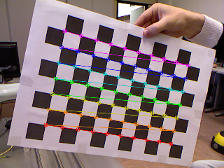 Image showing the RGB calibration target used to figure out camera parameters Image showing the RGB calibration target used to figure out camera parameters
-
EASY 3: C++ Code -- -JUST COPY AND USE THE CODE |
Also uses Code of Utility classes Matrix4 (4x4 Matrix) and Vect3f (3 element vector of floating points) and Vect2i (2 element vector of integers) --- Transforming from Depth->Color or Depth ->world X,Y,Z involves transformations (Matrix, vector calculations) --- these classes and the code that uses them have been created for you. Some languages like Java may have built in classes for these common mathematical elements.
Function to convert from Raw depth to Meters
NOTE: Raw depth values are integer between 0 and 2047
float RawDepthToMeters(int depthValue)
{
if (depthValue < 2047)
{
return float(1.0 / (double(depthValue) * -0.0030711016 + 3.3309495161));
}
return 0.0f;
}
Function to Convert from u,v,depth (called here x,y,depth) TO X,Y,Z (called here result.x, result.y, result.z)
Vec3f DepthToWorld(int x, int y, int depthValue)
{
static const double fx_d = 1.0 / 5.9421434211923247e+02;
static const double fy_d = 1.0 / 5.9104053696870778e+02;
static const double cx_d = 3.3930780975300314e+02;
static const double cy_d = 2.4273913761751615e+02;
Vec3f result;
const double depth = RawDepthToMeters(depthValue);
result.x = float((x - cx_d) * depth * fx_d);
result.y = float((y - cy_d) * depth * fy_d);
result.z = float(depth);
return result;
}
Function to Convert from X,Y,Z (called here pt.x, pt.y, pt.z) TO RGB pixel location (called here result.x, result.y)
Vec2i WorldToColor(const Vec3f &pt)
{
static const Matrix4 rotationMatrix(
Vec3f(9.9984628826577793e-01f, 1.2635359098409581e-03f, -1.7487233004436643e-02f),
Vec3f(-1.4779096108364480e-03f, 9.9992385683542895e-01f, -1.2251380107679535e-02f),
Vec3f(1.7470421412464927e-02f, 1.2275341476520762e-02f, 9.9977202419716948e-01f));
static const Vec3f translation(1.9985242312092553e-02f, -7.4423738761617583e-04f, -1.0916736334336222e-02f);
static const Matrix4 finalMatrix = rotationMatrix.Transpose() * Matrix4::Translation(-translation);
static const double fx_rgb = 5.2921508098293293e+02;
static const double fy_rgb = 5.2556393630057437e+02;
static const double cx_rgb = 3.2894272028759258e+02;
static const double cy_rgb = 2.6748068171871557e+02;
const Vec3f transformedPos = finalMatrix.TransformPoint(pt);
const float invZ = 1.0f / transformedPos.z;
Vec2i result;
result.x = Utility::Bound(Math::Round((transformedPos.x * fx_rgb * invZ) + cx_rgb), 0, 639);
result.y = Utility::Bound(Math::Round((transformedPos.y * fy_rgb * invZ) + cy_rgb), 0, 479);
return result;
}
|
Example using the above code
//visit every pixel in an depth Image and find its color RGB value and the true XYZ value
// where Xres is the number of pixels in the X direction (number of columns) and Yres is the number of pixels in the Y
// direction (number of rows).
// assumes RawDepth[u][v] is the raw depth image and RGB[i][j][f] is the RGB image captured where f =0 for Red, 1 for Green, 2 for blue
for(int u=0; u<Xres; u++)
for(int v=0; v<Yres; v++)
{
Vect3f WorldPoint = Vec3f DepthToWorld(u,v, RawDepth[u][v]); // this is the World X, Y, Z as
//get the color pixel location corresponding to the WorldPoint
Vect2i RGB_PixelLocation = Vec2i WorldToColor(WorldPoint);
//get the R,G,B value at this location
int R = RGB[RGB_PixelLocation.x][RGB_PixelLocation.y][0];
int G = RGB[RGB_PixelLocation.x][RGB_PixelLocation.y][1];
int B = RGB[RGB_PixelLocation.x][RGB_PixelLocation.y][2];
//print out values (but, you could store in some kind of Point Cloud data structure the X,Y,Z,R,G,B values)
cout << "X,Y,Z" << WorldPoint.x << WorldPoint.y << WorldPoint.z << " and R,G,B" << R << G << B;
PointCloud_Image[u][v] = PointCloud(WorldPoint,,R,G,B); ///create your own PointCloud class, calling constructor
}
|
|